 |
|
Your donations help keep this valuable resource free and growing. Thank you.
|
Temp and Fuel Gauge don't work |
Post Reply 
|
Page <1234 8> |
| Author | |
farna 
Supporter of TheAMCForum 
Moderator Lost Dealership Project Joined: Jul/08/2007 Location: South Carolina Status: Offline Points: 19676 |
 Post Options Post Options
 Thanks(0) Thanks(0)
 Quote Quote  Reply Reply
 Posted: Nov/08/2013 at 12:10pm Posted: Nov/08/2013 at 12:10pm |
|
And this will help on the gauges not working issue:
http://www.wps.com/AMC/dashreg/index.html A 63 Classic is shown, but this applies to any car with an external regulator. A Gremlin/etc. with the regulator built into the temp gauge can be fixed this way too, but you must take the gauge apart and solder wires to it to come out to the regulator. A bit more work, but if the points are bad or get corroded again after cleaning (as described above) this is a permanent fix. Well, more permanent -- the regulator can go bad or wires come loose. The regulator has to be grounded, but the gauges don't draw enough current to worry about mounting it on a heat sink. I've been running a similar setup since 1999 with no problems at all. |
|
|
Frank Swygert
|
|
 |
|
401MATCOUPE 
AMC Addicted 
Joined: May/20/2010 Location: Salisbury, MD Status: Offline Points: 5367 |
 Post Options Post Options
 Thanks(0) Thanks(0)
 Quote Quote  Reply Reply
 Posted: Nov/08/2013 at 2:58pm Posted: Nov/08/2013 at 2:58pm |
|
Be aware, AMC used General Time for the Matador Coupe and 4 door and Ambassador after 1974. The link Chuck posted is for Borg Clock. The General Time movement is not the same that is why I sent back to Instrument Services....they also sell the kits for Borg, which are fairly easy to repair/convert...I didn't ant to touch the General Time unit...the adjuster was broken in mine too. The repaired everything including made the lens like new...great value for the $$$.
|
|
|
Ross K. Peterson
68X,GoPac,343,AT,52A(1stCar) 68X,GoPac,390,4sp,52A 69X,GoPac,390,4sp,64A 70X,GoPac,390,4sp,87A,8 70X,GoPac,390,4sp,BBO,8 70 Jav SST,390,AT,BSO 74MatX,401,AT,Prototype 74MatX,401,AT |
|
 |
|
amcenthusiast 
AMC Addicted 

Joined: Jul/02/2012 Location: SW Atlanta GA Status: Offline Points: 1778 |
 Post Options Post Options
 Thanks(0) Thanks(0)
 Quote Quote  Reply Reply
 Posted: Nov/09/2013 at 6:59am Posted: Nov/09/2013 at 6:59am |
|
Thanks for your excellent explanation BUILD. Yeah, there are two electrically heated springs inside the Grem/Hornet type temperature gauge. As I understand it... the input voltage from the (yellow wire to instrument cluster printed circuit panel) ignition circuit supplies power to the first spring which has the contact points -they open and close, the spring-w-heating element calibrated to pulse around 5 volts, which then supplies the reduced voltage to the second electrically heated spring -that second one is the one that gets it's variable resistance ground from the sending unit (coolant temp send unit).
Yes; cleaning the contact points inside the temp gauge allowed voltage to 'wake up' my fuel gauge (as the temp 'CVR' supplies power to both the temp and fuel 'resistance readers'/gauges) but to my disappointment while both gauges began to operate, they both read to high because the 'CVR' spring is non-operational (it doesn't heat up and intermittently interrupt/open and close the points). So while I got them to work, they don't work correctly. I'll be checking out FARNA's advice; to solder in some type of resistor to replace the burnt out factory 'CVR' (yeah, not really a true voltage regulator?) I'm also interested to search for a replacement temp gauge unit that will simply swap into the factory instrument cluster. So far I've found an inexpensive Stewart Warner temp gauge that appears to have the same three stud mounting pattern but I don't know if it has the voltage reducer spring-w-contact points inside... yet As for the Rebel/Matador/Ambo (and Jav/AMXs) temp and fuel gauges, they all have an external three prong 'CVR' that plugs into the instrument cluster printed circuit panel -it looks like a 1 1/4" x 1/2" silver metal box. -if you don't have a temp or fuel gauge, and you've already checked the sending units with an ohmmeter, that's what to check next? -see if it completes a circuit by touching those prongs with an ohmmeter... The AMC clocks don't get voltage to operate from the reduced voltage dedicated circuit that powers the gauges -they get fused power directly from the fuse panel -either the fuse is blown, bad fuse connections, clock red wire is not plugged onto the fuse panel or the clock itself is failed? -usually a toasted/burnt/shorted winding inside the clock instrument itself? I bet BUILD knows and can tell us how to wire or solder in a resistor, to bypass a failed factory 'CVR'... what type of resistor? where to buy? Thanks all for patience and space on AMC Forum |
|
 |
|
slownugly 
AMC Nut 
Joined: Nov/23/2009 Location: PA Status: Offline Points: 293 |
 Post Options Post Options
 Thanks(0) Thanks(0)
 Quote Quote  Reply Reply
 Posted: Nov/18/2013 at 6:24am Posted: Nov/18/2013 at 6:24am |
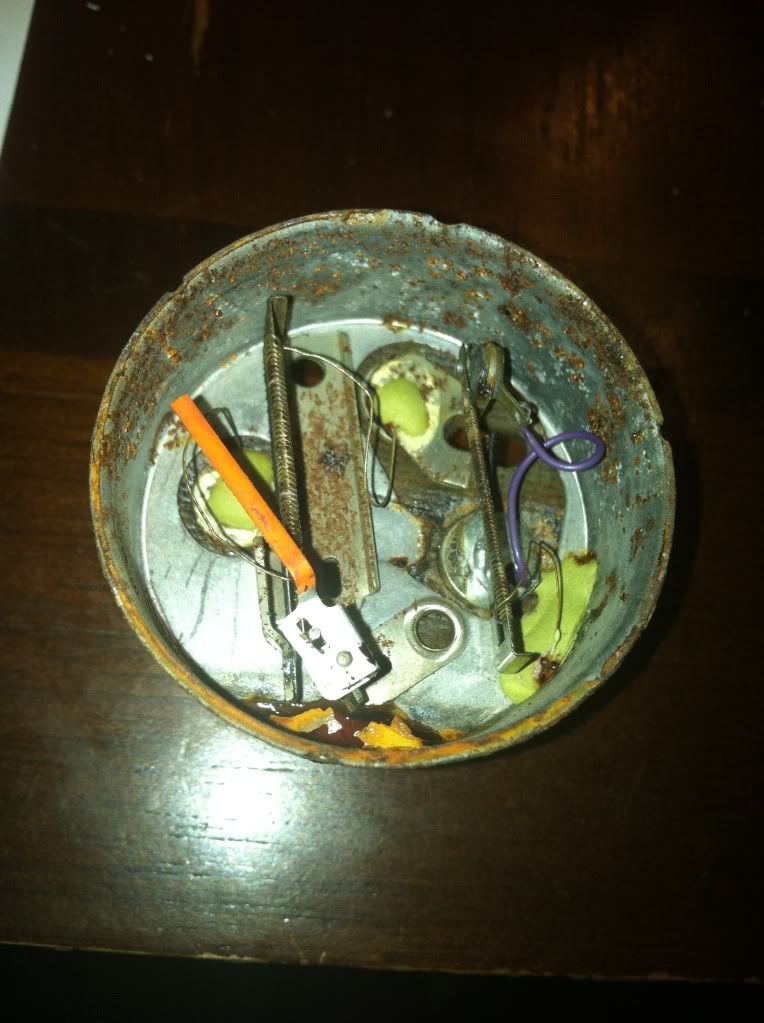
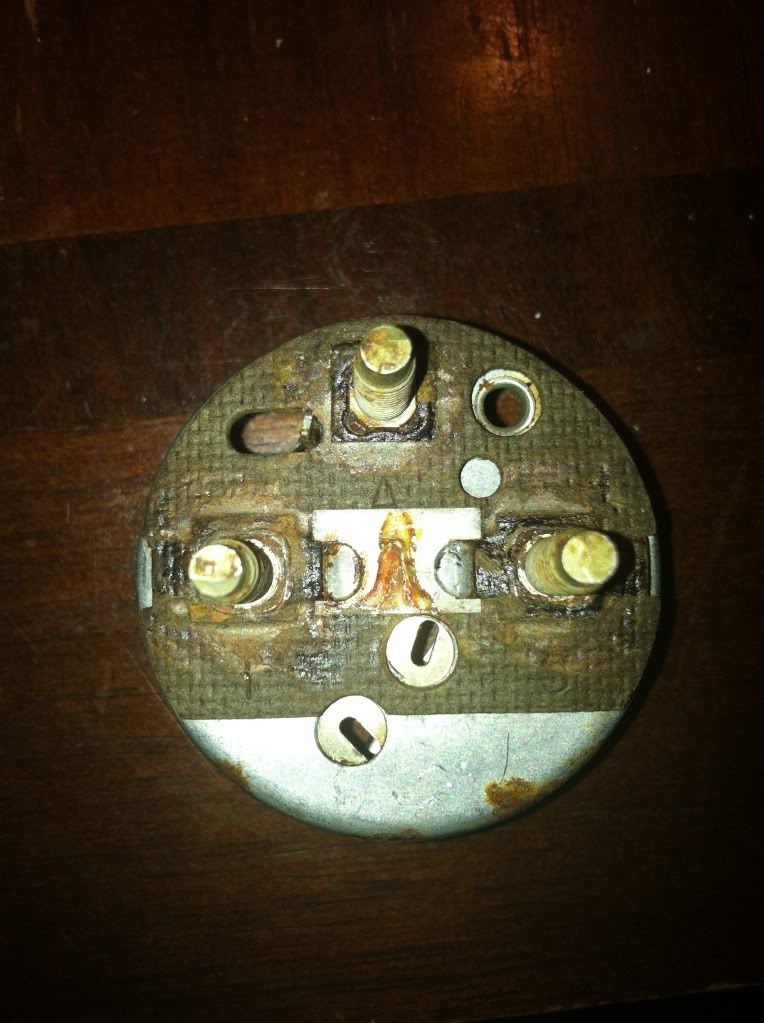
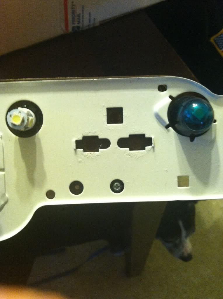
 I'm in the process of converting my 68 American to solid state. I'm not sure if the original works as i got the car after sitting many years, but I want longevity, accuracy, and reliability. The American has the regulator in the fuel gauge as pictured above. Gremlin and hornet are in the water temp gauge. Because American fuel gauges are hard to find I ordered an nos gremlin/hornet gauge for 30 shipped. They have the simple 2 bolt setup and I will be adding the external regulator. Basically, as I understand it, the purple wire coming in from the right stud is the 12 v. (I)The wire at the end of the coil is attached to the body of the gauge which is grounded ( see next paragraph for pic of how they ground the gauge) like bill described the contact points regulate the voltage out to an average and the 5 volt average goes to that top post. That post goes directly to the other gauge/s to supply the 5 volts. It's also soldered to the fuel gauge windings on the left on the inside as you can see. Then the 3rd and final post on the left is the signal (ground) coming from the fuel level sensor. The gauge is grounded in a way that should be noted as I can see this type of thing affecting gauge performance if someone is running an original setup.   In the back of the gauge there is a plate in the center. The other gauges without a regulator do not have that because that is the ground for the gauge body and ultimately the regulator. In the second picture you can see the 3 holes. Before I painted it there was a bare spot there for the ground to make contact with the metal background. I do not need this ground as I am grounding the external regulator through ground screws in the circuit. If you guys are interested I can post the rest of my results after I have this job completed. I'm going to bench test it all to make sure it's good. Heck I'll even use a fuel sensor to check the gauge. |
|
|
28 model a 73 gremlin drag car
74 gremlin project 00focus v8 5speed hot rod rollback 68 american mpg project |
|
 |
|
farna 
Supporter of TheAMCForum 
Moderator Lost Dealership Project Joined: Jul/08/2007 Location: South Carolina Status: Offline Points: 19676 |
 Post Options Post Options
 Thanks(0) Thanks(0)
 Quote Quote  Reply Reply
 Posted: Nov/18/2013 at 11:09am Posted: Nov/18/2013 at 11:09am |
|
Richard, that is a three prong solid state voltage regulator, not a resistor. The CVR in the temp gauge is technically an "averaging voltage regulator", though it does in fact reduce voltage, it still maintains an average of 5V. The solid state regulator will deliver a steady 5V. The gauges don't care, they will tolerate a full 12V without damage, but of course won't work correctly (as will the sending units) as the variable resistance will be way off.
A voltage reducer won't work because the charging system isn't a steady 12V. With the alternator or generator running voltage will fluctuate from 12V to 13.5V, and may drop below 12V depending on battery and charging system condition (and can go over 14V). So if you used a 7V reducer to get 5V from the 12V system it would be off a good bit at any given time. A regulator maintains a specific voltage regardless of input, though input must be higher than output for it to work. The old averaging CVR needs at least 10V to work correctly IIRC, but the little 7805 solid stat regulator only needs about 7V to work, but will tolerate something like 18V... IIRC. It will take anything a normally functioning alternator will dish out. |
|
|
Frank Swygert
|
|
 |
|
AMC1320 
AMC Apprentice 
Joined: Oct/22/2012 Location: Manchester, TN Status: Offline Points: 152 |
 Post Options Post Options
 Thanks(0) Thanks(0)
 Quote Quote  Reply Reply
 Posted: Nov/18/2013 at 6:20pm Posted: Nov/18/2013 at 6:20pm |
|
With the help of this forum I was able to diagnose each portion of the guage system with a meter, either looking for voltage or continuity , took some trouble shooting but ended up being the radio noise suppressor that was not passing voltage thru the fuel guage. Once I jumpered it it allowed voltage to get back to the sending unit and the fuel guage works perfectly now.
It was q process of ruling out each individual component until I found the culprit. Don't know why the noise suppressor failed, it's just a coil of fine wire, but it would not pass voltage thru it although visually it looked fine This was on a 69 Ambassador btw |
|
|
Rob C
69 Ambassador SST HT 81 Spirit 84 Eagle Limited (Daily Driver) 82 SX4 06 Commander |
|
 |
|
rocklandrambler 
AMC Addicted 
Joined: Feb/09/2013 Location: Nanuet, NY Status: Offline Points: 3953 |
 Post Options Post Options
 Thanks(0) Thanks(0)
 Quote Quote  Reply Reply
 Posted: Nov/19/2013 at 2:09am Posted: Nov/19/2013 at 2:09am |
|
I'm wondering if the suppressor actually failed or just by removing it you cleaned the connecting pins allowing your jumper to have a clean connection. That suppressor probably had been touched since it was installed about 44 years ago and some corrosion might have built up between the pins and the suppressor. But, you got the gauges working again which was the task you wanted to accomplish.
|
|
|
Past AMC's
1974 Hornet X (new) 1975 Gremlin X (new) 1964 Classic 660 Cross Country 1965 American 440-H |
|
 |
|
myther 
AMC Apprentice 
Joined: Jun/11/2009 Location: Los Angeles Status: Offline Points: 99 |
 Post Options Post Options
 Thanks(0) Thanks(0)
 Quote Quote  Reply Reply
 Posted: Nov/19/2013 at 2:28am Posted: Nov/19/2013 at 2:28am |
|
Glad to see you got your trouble shooted. I was having very similar problems but had a different solution. Always like to see how other people fix their problems.
|
|
|
'68 Rambler American 2dr post
'67 Rebel Hardtop |
|
 |
|
farna 
Supporter of TheAMCForum 
Moderator Lost Dealership Project Joined: Jul/08/2007 Location: South Carolina Status: Offline Points: 19676 |
 Post Options Post Options
 Thanks(0) Thanks(0)
 Quote Quote  Reply Reply
 Posted: Nov/19/2013 at 10:25am Posted: Nov/19/2013 at 10:25am |
|
Now you need to check the radio! If you use a modern FM radio you may not have a problem without the suppressor. If you still use the old original radio (AM or AM/FM) you might. You can get radio frequency interference (RFI) suppressors that go onthe alternator output. If you've upgraded to a GM style alternator it may not even be needed.
|
|
|
Frank Swygert
|
|
 |
|
RebelYell 
Supporter of TheAMCForum 
Joined: May/04/2011 Location: North Carolina Status: Offline Points: 824 |
 Post Options Post Options
 Thanks(0) Thanks(0)
 Quote Quote  Reply Reply
 Posted: Nov/22/2013 at 5:30pm Posted: Nov/22/2013 at 5:30pm |
|
Took the instrument panel out of the 77 Barcelona today and swapped out the CVR with a new one and the fuel and temp gauge still did not work. I needed to replace a couple burned out bulbs so at least I got something accomplished. Back to checking more wire circuits. I've not yet got a service manual for it but I wonder if the service manual for my 74 Matador would help me out on the wiring diagrams for the 77. Anyone know if there is any difference?
|
|
 |
|
Post Reply 
|
Page <1234 8> |
|
Tweet
|
| Forum Jump | Forum Permissions  You cannot post new topics in this forum You cannot reply to topics in this forum You cannot delete your posts in this forum You cannot edit your posts in this forum You cannot create polls in this forum You cannot vote in polls in this forum |